|
Rock Mass Strength based on Generalized Hoek-Brown Criterion
|
|||
|
|||
| References: |
Uniaxial Compressive Strength of Intact Rock σci Dialog
| Field estimate of strength | Examples | Uniaxial Compressive Strength (MPa) | |||
| Specimen can only be chipped with a geological hammer | Fresh basalt, chert, diabase, gneiss, granite, quartzite | ||||
| Specimen requires many blows of a geological hammer to fracture it | Amphibolite, sandstone, basalt, gabbro, gneiss, granodiorite, limestone, marble, rhyolite, tuff | ||||
| Specimen requires more than one blow of a geological hammer to fracture it | Limestone, marble, phyllite, sandstone, schist, shale | ||||
| Cannot be scraped or peeled with a pocket knife, specimen can be fractured with a single blow from a geological hammer | Claystone, coal, concrete, schist, shale, siltstone | ||||
| Can be peeled with a pocket knife with difficulty, shallow indentation made by firm blow with point of a geological hammer | Chalk, rocksalt, potash | ||||
| Crumbles under firm blows with point of a geological hammer, can be peeled by a pocket knife | Highly weathered or altered rock | ||||
| Indented by thumbnail | Stiff fault gouge | ||||
|
|||||
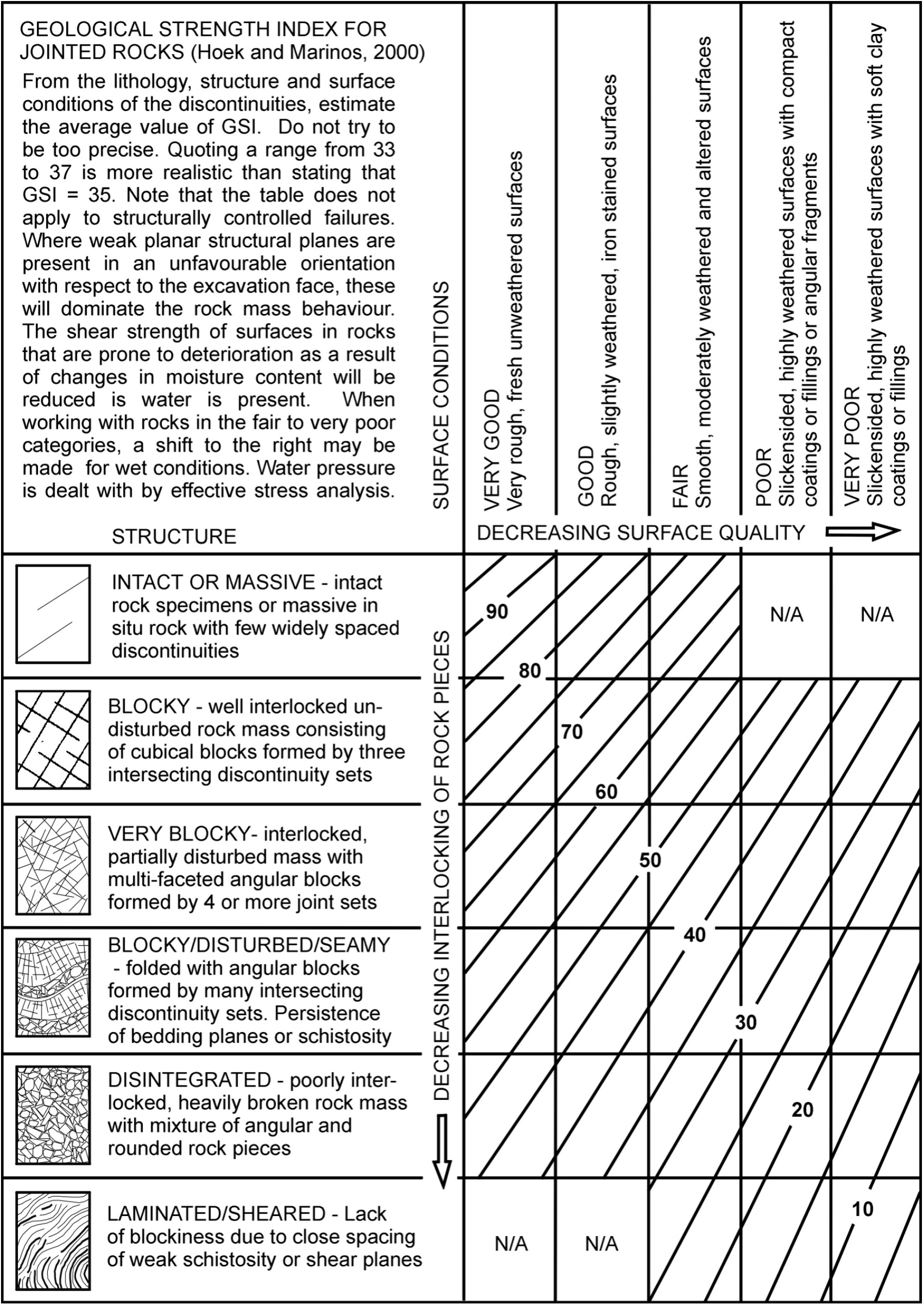
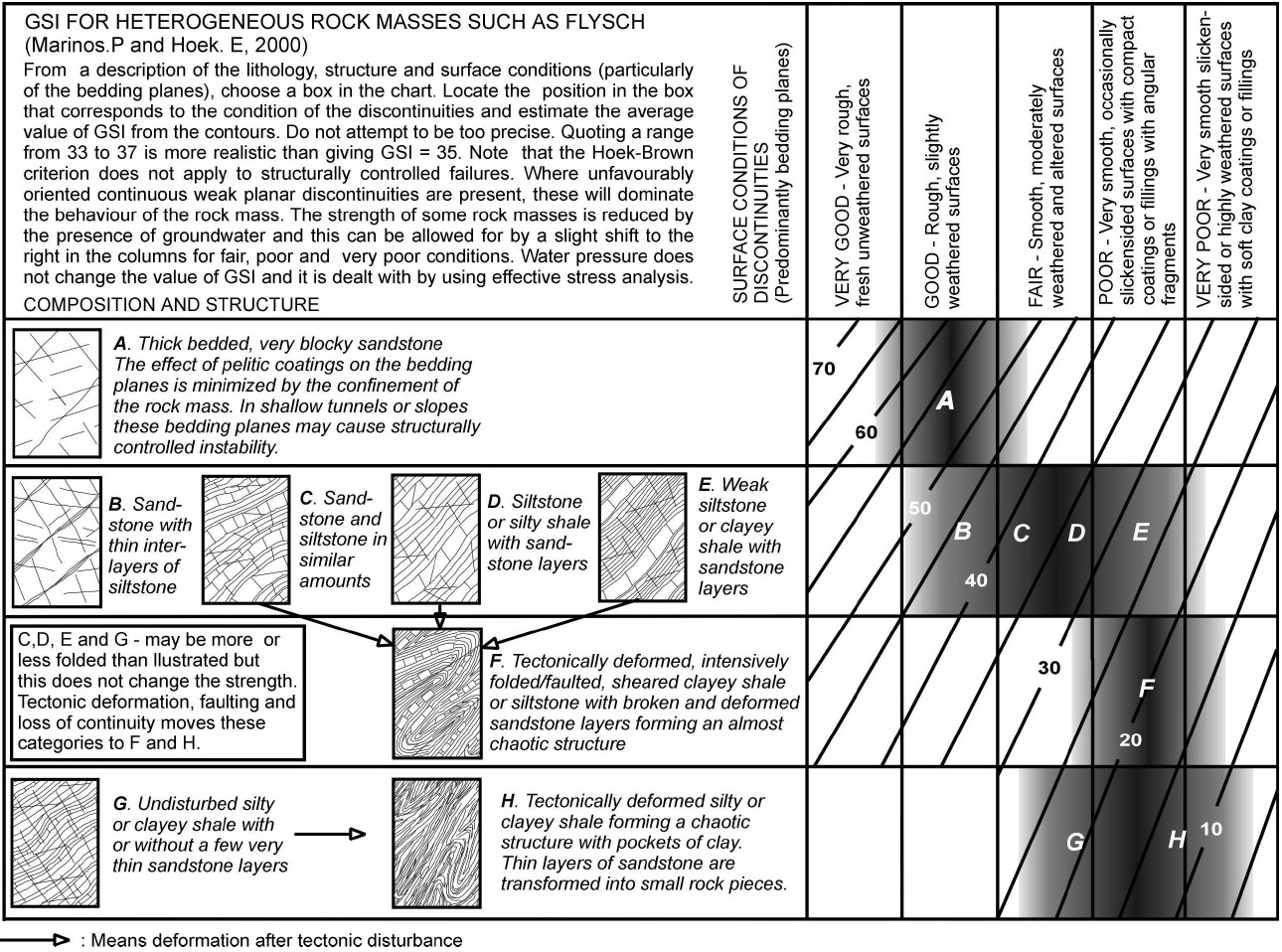
GSI Calculation Dialog

Mi Dialog
| Select mi value from the list and click x to close the dialog. | ||
Disturbance Factor (D) Dialog
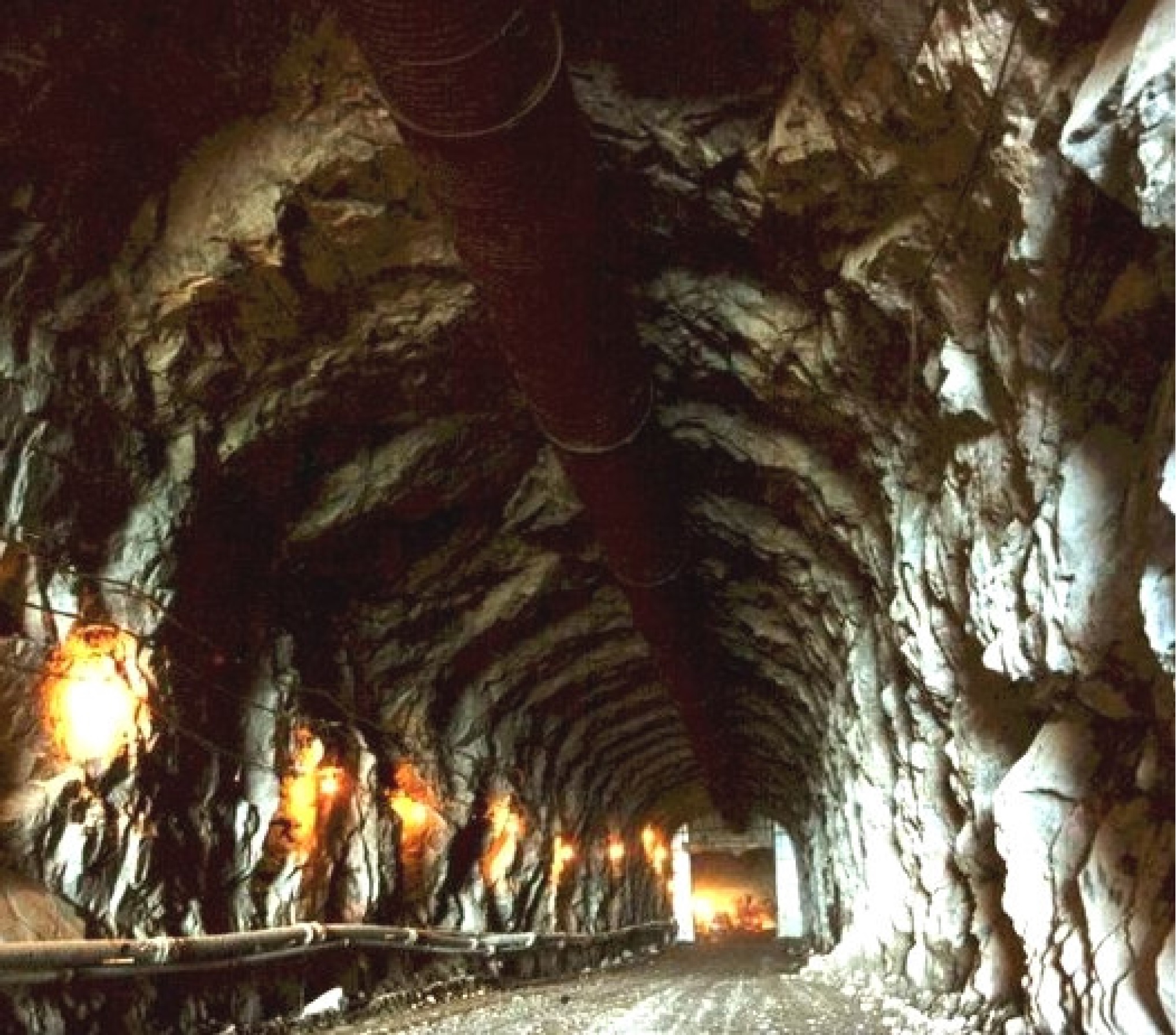
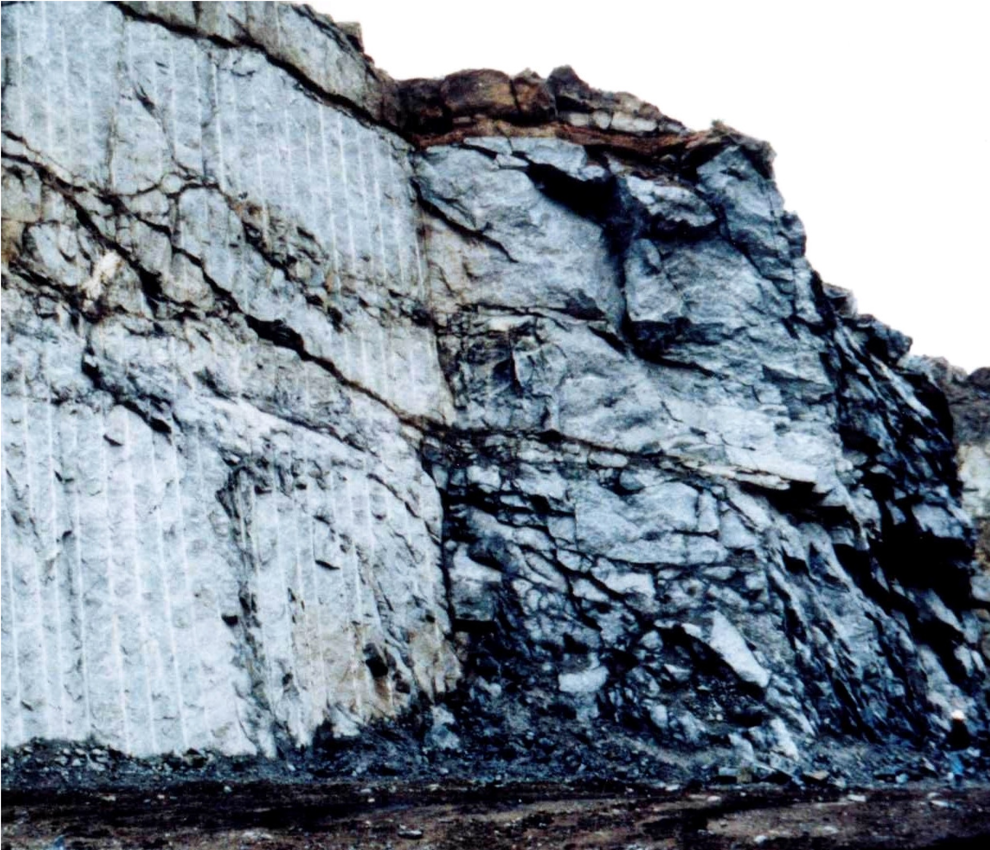
Tunnel
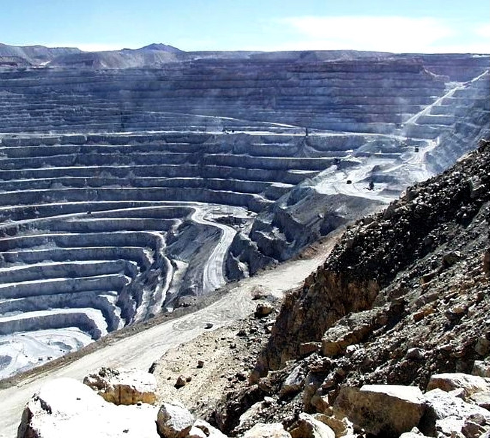
Slope
|
||||||||||||||
|
Intact Rock Elastic Modulus (Ei) Dialog
| Select the modulus ratio (MR). Intact modulus
(Ei) will be automatically calculated by multiplication of the modulus ratio (MR) by the
uniaxial compressive strength of the intact rock (σci): Ei = MR x σci |
||||||||||
|
|
||||||||||
关于...
Hoek-Brown强度准则在国际上已广泛应用于矿业工程、隧道工程、高边坡工程等行业,该方法的理论系统性和基于工程实践的合理性也逐渐被国内岩石力学学术界所认识与接受,但在设计、施工等工程界却尚未得到广泛应用。本网页旨在生产部门应用该准则提供便利的工具。
发展历程:
Hoek-Brown强度准则是用于预测岩石破裂的经验公式。1980年,Evert Hoek(津巴布韦裔加拿大人)和E. T. Brown(澳大利亚布里斯班人)两人在研究地下开挖工程时,推导出该经验公式;1988年,两人又合作发表文章,把该理论推广至露天开采和边坡稳定性的研究;2002年,Hoek等人引入地质强度指标(GSI)参数,给岩土工程师提供了定量分析岩体应力状态和Bieniawski的岩体质量指标(RMR)及地质强度指标理论(GSI)理论之间的关系,尽可能的反映原岩的各项物理参数以及岩体的结构面状态。2018年进一步更新了相关参数。
人物简介:
Evert Hoek (1933-2024),岩石力学专家,他于1958年开始研究南非深部金矿中的脆性岩石力学问题,并于1965年在开普敦大学攻读博士学位。同年他在英国帝国理工学院皇家矿业学院建立了岩石力学中心。1968年,他在那里开发了岩石力学三轴试验。1975年,他成为多伦多大学的教授,同时在温哥华的Golder Associates担任高级咨询工程师长达12年。退休后一直以独立咨询师的身份参与岩石力学研究与工程。
局限与改进:
二维Hoek-Brown(H-B)强度准则未考虑中间主应力影响,亚利桑那州立大学章连洋教授、同济大学朱合华教授等提出了Generalized Zhang-Zhu(GZZ)强度准则,以反映中间主应力对岩体强度的影响规律,揭示岩体强度和破坏模式在π平面和子午面上的双重非线性拉压(脆-延)转化规律,且与二维H-B准则共享参数体系,是真正意义上的三维H-B强度准则。该准则已被国际岩石力学界高度认可,本网页后续将增加该准则。
备注:
The front-end HTML code of this webpage is partly based on the work of Dr. Mikola.
|
Support Pressure Curve (Based on Longitudinal Displacement Profiles for Convergence Confinement Analysis) |
|||
|
|||
| References: |
关于...
1. 在二维有限元分析中模拟隧道开挖和支护时,需要通过施加支护力(support pressure)的方式来模拟掌子面附近发生的约束和松弛,这通常可以采用收敛-约束分析法和隧道纵向位移曲线。
2. 对于埋深较浅或者岩质较硬的隧道,预期隧道周边的收敛变形仍处于弹性阶段,此时,可以使用Panet(1995)提出、并被国际著名岩石力学专家Hoek等人(2008)肯定的经验公式进行评估,对于掌子面前方尚未开挖段,即围岩体内的变形量,则可以采用Unlu & Gercek(2003) 提出的经验公式进行评估。
3. 在埋深、或者高地应力、或者软岩情况下,隧道开挖可能会出现大量岩体屈服,在这些情况下,可以采用Chern(1998)提出的经验公式进行评估。
4. Vlachopoulos和Diederichs(2009)的进一步研究表明,Panet, Unlu & Gercek提出的纵向位移曲线合理性的前提是塑性区的半径不超过2倍隧道半径,并且隧道掌子面前方的屈服区未与隧道四周的屈服区贯通。 否则,他们建议对Chern提出的曲线进行修正,具体地说就是引入了归一化塑性区半径,R*=Rp/Rt,其中Rp代表塑性区的半径。
5. 本网页同时对隧道开挖模拟过程中各施工步(staging)的设定、以及对应的支护压力比例提出了建议。
6. 更详细的背景知识可参阅参考文献。
|
Support Stiffness vs Time Curve |
||||||||||||||||||||||||||||||||||||||
|
||||||||||||||||||||||||||||||||||||||
About...
1. As the strength and elastic modulus of sprayed concrete are related to its age, the development of the stiffness of the sprayed concrete lining over time (or distance from the face of the tunnel) should also be considered when using finite element analysis for calculation.
2. Knowing the development process of stiffness EA and EI over time, the stiffness reduction factors for each construction step can be set in finite element software, such as in Rocscience RS2.
3. fci=fc28*e(s*(1-sqrt(24 * 28 / t))), s refers to strength gain factor, 0.33 as default.
4. Eci=0.043*ρ1.5*sqrt(0.9*fci*(1.2875-0.001875*fci)), ρ refers to density, 2400kg/m3 as default.
5. This tool can consider spraying the sprayed concrete lining in up to 5 times, with the option to set the "thickness of each layer t (mm)" separately. The time interval between the two sprays is the "duration of each shift (h)". During this time interval, the tunnel advances forward by one "construction step distance (m)".
6. This tool also provides calculation of support force, including Panet's (1995) empirical formula and Chern's (1998) empirical formula. For more detailed background knowledge, please refer to the "Support Pressure Time Curve" tool.
StageCapacity(M-N Diagram)
|
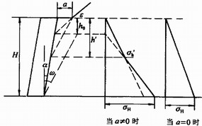
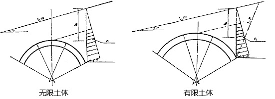
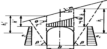
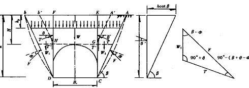
隧道洞门土压力荷载 |
明洞设计荷载计算 |
偏压隧道衬砌荷载 |
深埋/浅埋隧道荷载 |
|
Rockburst Proneness Index (RPI) Calculator |
|
Canopy designer |
||
|
|
|
|
|
Rock-support Interaction |
||
|
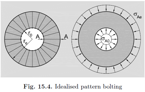
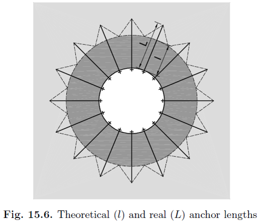
Ground stiffenining by pre-stressed anchors |
|
|
|
| Reference: Kolymbas, Tunnelling and tunnel mechanics - a rational approach to tunnelling, 2005 | |
|
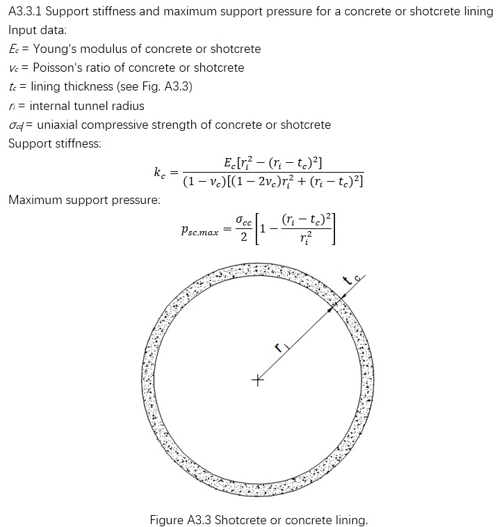
Shotcrete - Equivalent Support Pressure |
|
Tunnel Blasting Design |
|
Set up detonator delay for each blast hole group (no more than 10 groups)
Set up parameters for automatic blastholes layout